

New mouthpiece for our Artist Series Irish Whistle
This is part I of a series about our new Artist head. Originally written in Dutch, please bare with us as we try and translate the complete series. We’ll try and avoid writing this article in ‘Denglish’ (no Google translate is used here, folks). In our permanent quest looking to improve our products, we have also started looking into improving our whistle heads. You may know that we’ve started printing in 3D for some of our parts a few years ago. Especially for whistles, this has proven to be a technique with many advantages; different materials, colors, and finishes are very interesting and still evolving.
For 3D printing, we are using a so called ‘filament’; a smal round plastic thread, 2.85 of 1.75 mm thick is pushed through a hot-end. This hot-end melts the filament at a temperature of around 200-250 C (depending on the material used). The filament is pushed through a nozzle (around 0.4mm), and as a result the print head puts a layer of 0.1mm on the previous layer according to a pattern, determined by x-, y- and z-values (remember your math teacher talking about this?), along with other commands controlling extruder and temperature of the hot end. This code is called a g-code. The software processes these codes and converts them into control commands to stepper motors, who in turn move the printer head and the extruder.
3D printing also has its disadvantages: it takes long before you actually have a print, and the maximum resolution is 0.1mm, although the latest printers can go much finer. Okay, we’re did not intend to write this article about 3D printing. Let’s have a look at the design of the Artist Whistle head.
Part I – Introduction | Part II – Design | Part III – Simulations (still partly in Dutch, working on translations!)
What do we want to achieve with this series of articles? Well basically just to tell you how we have approached our R&D in trying to come up with a new improved mouthpiece for our Low and High whistles. We’re not claiming we’re the best out there, but we are certainly proud of what we do and since we’re musicians ourselves, we know what it’s like when you are searching for the right tools. While this is our standard mouth piece for our Artist and Standard Series Whistles, we also have an all aluminium Pro Series. All of our instruments are mostly hand made.
Written by Ruud Roelofsen (design, 3D)
Problem description
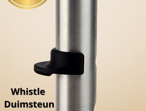
Before you improve something, you should have a problem, right? Well actually, we didn’t. We just started to experiment with our whistle heads design. Our Artist Series whistle heads are printed a carbon-fill filament. It’s a PETG with 20% carbon fibers. The PET (PolyEthylene Tereftalate) material is known because you buy them as drinking bottles at the supermarket. Fully recyclable and food safe. The filament (PET modified with glycol) is extremely water repelent. Sounds ideal for a mouth piece, right? However, the filament is pretty rough to the touch, which means the object need finishing. Picture below: unfinished object and a piece of non-printed filament.

Finishing means filing and sanding with different grain sizes (up to 3000). The downside is here that we’re removing material from the mouthpiece, so we have to take this into account while designing. Especially at the blade of the mouthpiece, it is crucial we have a precise print. This needs to be done with care, since the blade determines how, when and at which distance from the windway (or ‘duct’) the air is being split. The end of the duct sometimes has a chamfer. Subsequently, all these variables have an effect on how the mouth piece ‘projects’ the sound, whether it plays easily or not, and whether sounds ‘airy’ or not. The tip of the blade has a certain angle, and the top and bottom are called the over- and undercut of the blade (if any).
So the blade is where air, generated by the musician, is cut after it leaves the windway. In the picture below, the blade clearly has a sharp edge; this is where the air is ‘broken’. This is needed as the air oscillates below and above the blade at great speed. This is why we can hear the air starting to produce a tone, even without having a body attached to the mouthpiece. The area below the blade is called the chamber and determines the ‘color’ of the tone (among other things). The chamber leads to the body. The body has a certain ‘bore’ (diameter). The bore does not only affect playability, but also sound. For every type of whistle there is an optimal bore, although we also make high whistles with a ‘big bore’. So while there is flexibility in all of these variables, we are ultimately limited by physics or ergonomics, if not pure sound.

So we have seen that part of the problem of 3D printing is the time it takes to produce and finish mouthpieces. It takes about 30 minutes to fully finish a carbon printed mouthpiece. Important is to print the mouth piece with a 100% infill, so completely solid.
A normal 3D printer takes about 7 hours to print our mouthpiece with a resolution of 0.1 mm. If you speed up the printer, you may end up with gaps in your print. Too slow and you may have blobs sticking to your object.
So, for our new design, we are looking for quicker prints and a faster finish process without loosing any of the musical characteristics (or if possible, improve them).
Testing without prototyping?
From here, we are starting to look at characteristics. Could we improve our existing mouth piece? How to test this without designing and prototyping based on trial and error? Is change good? So why change? Of course we knew our existing mouthpiece inside- and out. With todays computers, designing has become much easier. Most of the software out there does a good job of setting up a design. In addition to that, simulation has gradually become part of a design; ket the software know what material you are working with, what kind of simulation you want to do and the results can be pretty amazing! This way, you can check basic characteristics, even without having a physical model at hand. Characteristics of a material can be strength, temperature, resonance, turbulence, acoustical variance and so on.
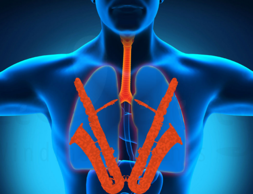
So, in our model, we are going to do a ‘flow-simulation’; we can virtually blow air into the mouth piece and see what happens. The computer shows us what happens to an air stream when air is blown into the windway. Important in this simulation is to look at air speed, temperature and humidity (not that important). We are working with air speeds of 1.0-1.5 mtr/s.

In the picture you can see the result of a certain set of variables used to generate a stream of air blown into the windway. We can see speed (color) and turbulence. What we immediately notice here is that some of the air is turned into a circulair movement before finding its way into the body.
Creating a new design
As mentioned, there are many software programs that do 3D design. So how do you go about creating a mouth piece? Step 1: start with a circle that is wide enough to fit the body of the whistle or flute:

A circle in a plane
After drawing a circle, we can create an extrusion or a cut based on that same circle. We can build a solid cylinder, or a tube with a certain thickness (thin feature).
By drawing a combination of shapes in certain key planes with key dimensions, and after giving them form and function, we build an object. Shapes can have mathematical features, but we can also draw freely into most program. You probably got it; possibilities are endless! A body is of a certain material, and is called a ‘part’. Many bodies can be part of an ‘assembly’. Parts can be static or move in the assembly.
.
Step 2: Or, or on top of this first drawing we can make new planes, on which we can create other drawings.

Extruded circle
You can build solids or cuts out of drawings. Below, you can see the Artist mouth piece as a complete solid model, without any cuts. So what we are missing is the windway, the window and the blade, as well as the chamber. While making cuts, we can shape the cut by using additional drawings and guide curves.

deQuelery Artist head – copyright deQuelery Windinstruments
The windway is a pretty important part; this is where the air is given its speed and direction, but it also determines the ‘pressure’ felt by the musician while playing. If you make the windway too small, blowing into the mouth piece can be felt as being difficult, with resistance. Too wide, and the musician is loosing air too easily and blowing octaves can be impossible (blowing octaves requires the air to go faster, so the musician needs to blow harder into the mouth piece). The sound, the amount of air heard into the tone and the resistance felt by the musician are important topics in itself and creates often lengthy debates because they are both perceived as very personal as well as they can vary per music style.
All in all, the mouth piece needs to be effective, needs to be playable and produce a tone without too much effort.
On with our design. After creating the model, giving it its characteristics like the material that the object is made of, we can render the complete design with photorealistic precision. This is called a ‘rendering’.

In the picture you can see an early design as a photorealistic rendering; lights, reflections, colors are all variables that can be changed.
This was Part I of a series of V. In Part II we are going to look closely to material characteristics and how the Artist mouthpiece is shaped into a more final model while doing more simulations.
In the next series we will explain how the final model is tested by doing a set of simulations, how it is converted into a printable design and how finishing is done.
Jump to part II Part III – Simulations (in Dutch, sorry – working on translations!)


Leave A Comment